

ROTARY R1070 Wireless Aligner, PRO CCD Alignment System
Rotary R1070 Wireless Aligner Pro CCD - Professional 3D Alignment System Without Fixed Towers
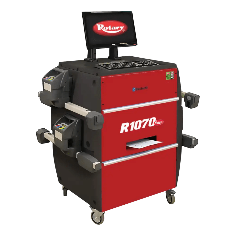
The Rotary R1070 is a professional 3D wireless wheel alignment system that uses eight CCD sensors to measure vehicle alignment angles accurately without fixed alignment towers. Built around a mobile wheeled console with integrated PC, monitor, and printer, this system delivers flexible bay deployment and consistent alignment measurements for automotive repair shops, tire dealers, and alignment-focused service centers.
Key Features & Benefits
8-CCD Wireless Sensor Architecture
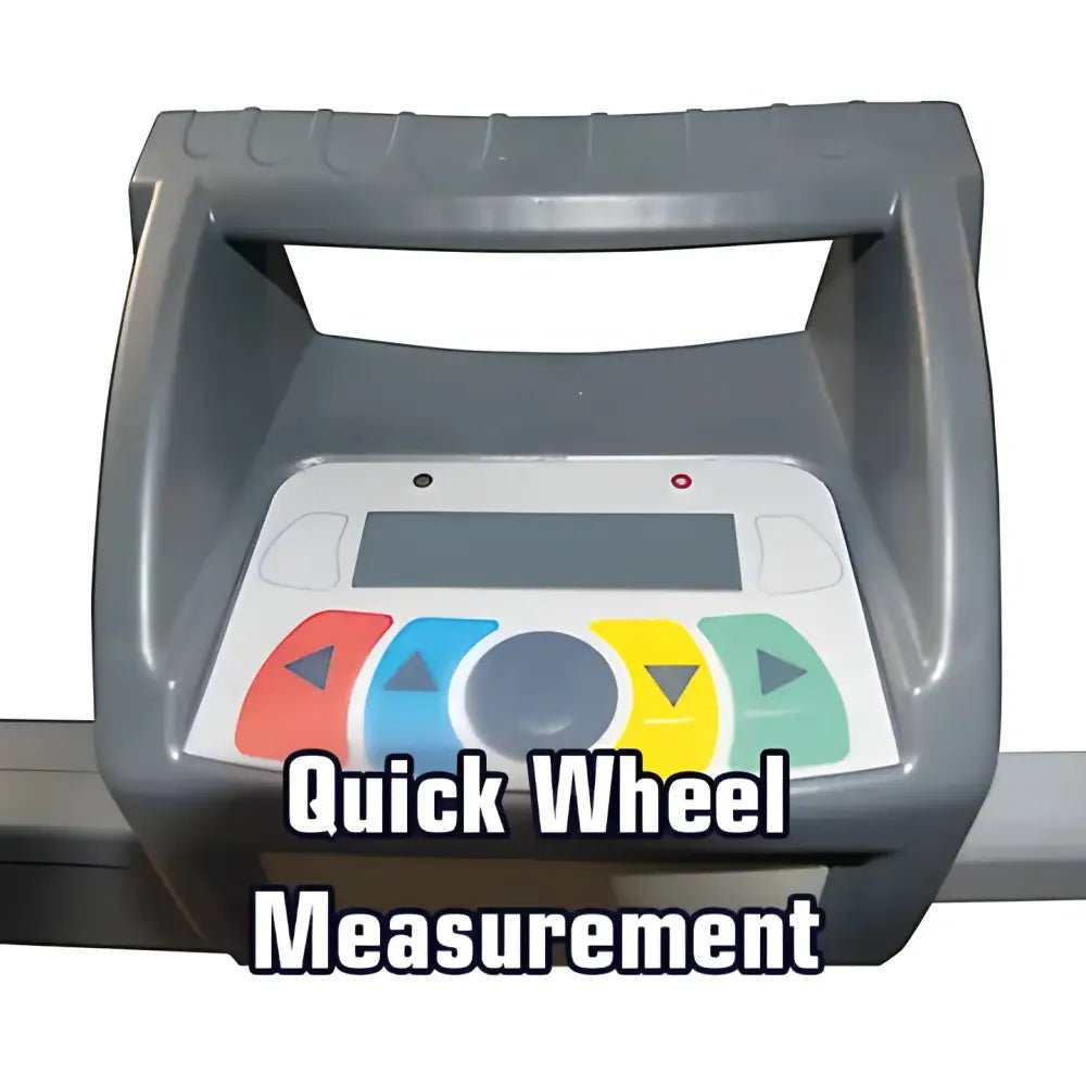
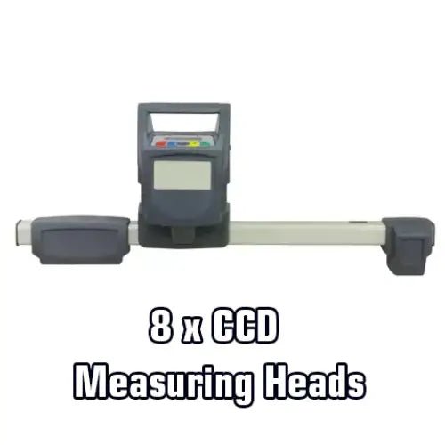
This model employs eight CCD sensors organized in four measuring heads that detect vehicle alignment angles through optical scanning. The wireless architecture transmits measurement data via Bluetooth and infrared communication without requiring cable connections to a fixed tower or alignment pit infrastructure.
Traditional fixed-tower alignment systems require expensive floor-mounted infrastructure and restrict vehicle positioning flexibility. The R1070's wireless approach addresses this industry-wide challenge by allowing wheel alignment measurement from any position on the shop floor, adapting to facilities with constrained layouts, multiple service bays, or high-throughput operations.
This enables flexible alignment workflows in shops where floor space is limited or bay configurations vary. Technicians can relocate the system between bays, adjust vehicle positioning freely, and reduce setup time compared to conventional stationary systems.
Integrated Mobile Wheeled Console
The system is built around a mobile wheeled cabinet that houses all hardware components—CCD sensors, quick-lock tire clamps, integrated PC with 19-inch monitor, and A4 printer—in a single integrated unit. This consolidation eliminates the need for separate workstations, sensor storage, and print infrastructure scattered across the bay.
Traditional alignment setups require technicians to move between multiple stations: sensor head storage, a remote PC workstation, printer area, and clamp locations. The R1070 addresses this operational inefficiency by delivering all tools needed for alignment measurement, processing, and documentation within one portable wheeled platform.
This improves workflow efficiency by reducing technician movement during alignments and enabling rapid repositioning between service bays. The mobile design also maximizes shop floor flexibility, allowing relocation to accommodate vehicle delivery schedules or bay prioritization changes without infrastructure modifications.
Patented Quick-Lock Tire Clamp System
The R1070 features patented quick-locking tire clamps that grip wheel rims with consistent clamping force and enable single-motion wheel attachment. The clamp design accommodates a range of wheel diameters and rim widths typical of passenger cars and light trucks without requiring manual adjustment between vehicles.
Standard clamp systems either require manual tightening (adding setup time and risking inconsistent grip) or use simple mechanical locks that may slip under measurement stress when wheels are repositioned or bumped during service. The patented quick-lock design addresses this industry-wide challenge by providing automatic secure grip on first engagement.
This reduces wheel setup time and eliminates clamp slippage during measurement cycles, which can cause alignment reading errors. The faster engagement also improves technician efficiency and reduces fatigue from repeated manual adjustments across high-volume alignment operations.
Comprehensive Angle Measurement Capability
The system measures toe (total and partial), camber, caster, thrust angle, set-back, and king pin angles with precision typical of professional-grade alignment equipment. Measurement data is processed by integrated alignment software that compares readings against factory specifications accessed through a vehicle database organized by VIN or model selection.
Basic alignment systems measure only toe and camber, requiring manual consultation of service manuals or secondary references for other angles. The R1070's multi-angle capability addresses the need for comprehensive suspension diagnostics by delivering all critical angles in a single measurement session, reducing the time technicians spend researching vehicle specs and cross-checking measurements.
This enables more thorough suspension analysis and faster diagnosis of alignment problems caused by suspension geometry issues, worn components, or accident damage. Complete angle measurement also supports preventive maintenance by identifying borderline conditions before they accelerate tire wear or affect vehicle handling.
Integrated PC with Large Vehicle Database
The system includes an integrated PC with 19-inch display monitor and comprehensive vehicle database accessible by VIN lookup or model/year selection. Factory alignment specifications are automatically populated when vehicle identification is entered, eliminating manual reference searches and reducing specification entry errors.
Manual alignment workflows require technicians to access separate service manuals, use multiple digital resources, or rely on printed specification sheets to determine correct alignment angles for each vehicle. The R1070 addresses this source-of-error challenge by embedding factory specifications directly in the system and keyed to vehicle identification.
This improves accuracy by ensuring correct specifications are used for every vehicle and accelerates workflow by eliminating research steps. The integrated monitor also displays alignment graphics showing current vs. specification angles in real-time, helping technicians visualize adjustment progress and confirm completion.
On-Board A4 Printer for Documentation
The included A4 printer produces alignment reports that document pre-adjustment angles, post-adjustment angles, and specification compliance. Reports are generated directly from the system and can be provided to customers or retained in service records without requiring data transfer to remote printing infrastructure.
Without on-board printing, alignment documentation requires transferring data from the alignment system to a separate office computer and printer, adding workflow steps and creating opportunities for data entry errors or lost information. The R1070 addresses this by providing immediate documentation at the alignment station.
This enables faster job completion and customer handoff while maintaining complete documentation of work performed. Technicians can provide customers with printed proof of alignment work completed and angles achieved, supporting customer confidence and potentially reducing alignment-related warranty disputes.
Applications & Use Cases
- Automotive Repair Shops: General-purpose wheel alignment for passenger cars and light trucks, integrated with brake, suspension, and maintenance service bays where alignment is periodic rather than primary focus.
- Tire and Wheel Alignment Specialists: Dedicated alignment facilities performing high-volume alignments, tire sales with alignment service, and wheel balancing combined with precision alignment measurement.
- Fleet and Commercial Service Centers: Regular alignment maintenance for fleet vehicles, commercial trucks, and service vehicles requiring periodic wheel alignment to manage tire wear and operational costs.
- Collision Repair Shops: Post-accident suspension alignment verification and adjustment, confirming vehicle geometry restoration following frame straightening or suspension component replacement.
Technical Specifications
| Specification | Value |
|---|---|
| System Type | 3D wireless wheel alignment system |
| Sensor Technology | 8 CCD sensors (4 measuring heads) |
| Communication Protocol | Bluetooth and infrared wireless |
| Measurement Method | Optical CCD scanning without fixed towers |
| Specification | Value |
|---|---|
| Integrated Computer | PC with alignment software and vehicle database |
| Display Monitor | 19-inch integrated monitor |
| Printer | A4 integrated printer for alignment reports |
| Console Design | Mobile wheeled cabinet for complete system assembly |
| Specification | Value |
|---|---|
| Toe Measurement | Total toe and partial toe (individual wheel) |
| Camber Measurement | Left and right camber angles |
| Caster Measurement | Left and right caster angles |
| Additional Angles | Thrust angle, set-back, king pin angle |
| Specification Database | Large vehicle database, VIN or model lookup |
| Component | Description |
|---|---|
| Wireless CCD Sensor Heads | 8 CCD sensors (4 complete measuring heads with wireless communication) |
| Mobile Wheeled Console | Cabinet housing integrated PC, 19-inch monitor, and A4 printer |
| Quick-Lock Tire Clamps | Patented clamps with automatic grip engagement |
| Brake Pedal Depressor | Tool for securing brake pedal during measurement |
| Steering Wheel Lock | Device for centering and locking steering position |
| Instructional Media | Setup and operation guides (format varies by supplier) |
| Specification | Value |
|---|---|
| Electrical Supply | 110 V, single-phase, 60 Hz |
| Infrastructure Required | None (no fixed alignment towers or pit mounting) |
| Installation Surface | Flat automotive shop floor suitable for vehicle positioning |
Installation Requirements
Shop Floor & Facility
- Surface: Flat, level automotive service floor typical of alignment bays with sufficient clearance for vehicle approach and sensor positioning
- Bay Dimensions: Standard automotive service bay with room for wheeled console positioning and vehicle wheel access
- No Fixed Infrastructure: No alignment towers, pit mounting, or floor anchors required; system operates as a mobile unit
Electrical Requirements
- Supply Voltage: 110 V single-phase, 60 Hz standard
- Power Connection: Standard shop electrical outlet suitable for workshop equipment
- No Special Wiring: No dedicated circuit upgrade or specialized power infrastructure required beyond standard shop electrical service
Installation Notes
- Portable Setup: System is mobile and can be positioned in any service bay with electrical access; relocation between bays does not require reinstallation
- Professional Installation: Installation and initial system setup should be performed per manufacturer installation manual to ensure sensor calibration and software configuration accuracy
- Local Codes: Verify compliance with local electrical codes and OSHA requirements before operation in your facility
Shipping & Delivery
Freight Coverage
Delivery: Freight shipping standard for this equipment. Coverage terms and free shipping availability vary by dealer; confirm specific shipping costs and terms with your sales representative.
Installation Services: Select authorized dealers offer free installation and setup services as part of equipment purchase. Confirm installation inclusion and scheduling during order placement.
Delivery Requirements
Equipment Needed: Forklift or pallet jack with sufficient capacity (consult dealer for specific weight specifications) required for unloading freight shipments at your facility.
Receiving: Inspect all packages and equipment before signing bill of lading. Report any visible damage to the freight carrier immediately; document all damage observations in writing.
Concealed Damage Reporting
Damage Claims: Concealed damage claims must be reported to the freight carrier and supplier within specified timeframe (typically 15-30 days depending on carrier policy). Contact your dealer for specific claim procedures and deadlines applicable to your shipment.
Warranty Coverage
Standard Warranty Program
3 Years - Parts: All component parts including sensors, PC, monitor, printer, clamps, and mechanical assemblies covered for defects in materials and workmanship
1 Year - Labor: Labor for repair and replacement of defective components
Warranty Requirements
Installation: Warranty coverage is valid when installation is performed by qualified personnel following the manufacturer installation manual
Maintenance: Continued warranty coverage requires adherence to manufacturer maintenance and care guidelines
Non-Transferable: Warranty is valid for the original equipment purchaser only and does not transfer with equipment resale
Ready to Add Wireless Alignment to Your Shop?
Get expert guidance on deploying the Rotary R1070 in your facility. Our team can help with product specifications, installation planning, and bay configuration.
Frequently Asked Questions
How many CCD sensors does the Rotary R1070 include and what angles can it measure?
The R1070 features 8 CCD sensors organized in 4 measuring heads that work together to detect vehicle wheel angles. This multi-head wireless architecture provides comprehensive optical coverage for measuring toe (total and partial), camber, caster, thrust angle, set-back, and king pin angles in a single alignment session. The eight-sensor design allows simultaneous measurement of all four wheels without repositioning, supporting efficient high-volume alignment workflows in busy shops.
What wireless communication methods does the Rotary R1070 use and how does this benefit shop operations?
The R1070 uses Bluetooth and infrared wireless communication to transmit measurement data from the sensor heads to the integrated PC without cable connections. This wireless approach eliminates the cable clutter and infrastructure constraints of fixed tower systems, allowing sensor heads to be positioned flexibly anywhere on the shop floor. Technicians can perform alignments in any service bay, adjust vehicle approach angles freely, and relocate the entire system between bays without requiring tower repositioning or infrastructure modifications.
What components and accessories are included in the complete Rotary R1070 system package?
The complete system includes 8 wireless CCD sensor heads in 4 measuring head assemblies, a mobile wheeled console that houses the integrated PC with alignment software and 19-inch monitor, an A4 printer for generating alignment reports at the service bay, patented quick-lock tire clamps that grip wheels without manual adjustment, a brake pedal depressor tool for securing the brake during measurement, a steering wheel lock for centering wheel position, and instructional media covering setup and operation procedures. This comprehensive package provides all hardware and tools needed for complete alignment operation without requiring additional accessory purchases.
What electrical power specifications and installation requirements does the Rotary R1070 need?
The R1070 requires standard 110 V, single-phase, 60 Hz electrical supply, which is typical of shop equipment and available in all automotive service facilities. The system connects to a standard shop electrical outlet without requiring dedicated circuits, specialized wiring, or power infrastructure modifications. This allows rapid deployment in any service bay with standard electrical service. Unlike fixed-tower systems, the R1070 requires no floor anchors, pit mounting, or ceiling clearance requirements, making installation straightforward in existing shop configurations without renovation or facility upgrades.
What vehicle types and wheel sizes are compatible with the quick-lock tire clamps?
The patented quick-lock tire clamps are engineered to accommodate the wheel diameters and rim widths typical of passenger cars and light trucks, covering the vast majority of vehicles serviced in general automotive repair facilities. The quick-lock design provides automatic grip engagement on wheel contact without requiring manual adjustment, dial-in procedures, or configuration changes between different vehicle sizes. This fast-engagement clamp system improves technician efficiency by eliminating setup steps and supporting rapid wheel positioning during high-volume alignment operations.
How does the integrated vehicle database help with alignment specification accuracy?
The R1070 includes a comprehensive vehicle database that technicians access by entering the vehicle VIN or selecting the model and year. When vehicle identification is entered, the system automatically retrieves and displays the correct factory alignment specifications for that specific vehicle model, eliminating the need to manually consult service manuals or reference materials. This automated specification population reduces data entry errors and speeds alignment workflow by ensuring correct target angles are displayed before measurement begins. Technicians can immediately see the factory toe, camber, and caster specifications they need to match, supporting faster and more accurate alignment completion.
Does the Rotary R1070 require fixed alignment tower infrastructure for installation?
No. The R1070 is a completely mobile wireless system that operates without fixed towers, pit mounting, floor anchors, or ceiling-mounted infrastructure. The system arrives as a self-contained wheeled console that technicians position on the shop floor like any mobile equipment. This mobile design eliminates the capital expense and facility downtime associated with installing traditional alignment towers, ceiling-mounted components, or floor-embedded anchoring systems. The absence of fixed infrastructure also enables rapid relocation between service bays, allowing shops to move the system to prioritize high-volume areas or adapt to changing service demands without requiring reinstallation or recalibration.
What warranty coverage and support are included with the Rotary R1070 system?
The R1070 includes a comprehensive warranty program providing 3 years of coverage for all component parts including sensors, PC hardware, integrated monitor, A4 printer, tire clamps, and mechanical assemblies. Labor coverage extends for 1 year, covering repair and replacement of defective components identified during that period. Warranty validity requires that installation be performed by qualified personnel following the manufacturer installation manual and that the equipment owner adhere to recommended maintenance procedures. The warranty is non-transferable and valid only for the original equipment purchaser; it does not extend to subsequent owners if the system is resold.
About the Brand